Objective: The aim of this scanning electron microscopic study was to investigate the interface characteristics between acrylic resin and five different types of fibres, which are thought to play an important role in the reinforcement of the denture base. The fibres used are poly methyl methacrylate, polyethylene, glass, carbon and silk.
Methods: Initially 140 poly (methyl methacrylate) denture base resin specimens reinforced with different fibres in a longitudinal and woven orientation was prepared for testing both transverse bend and impact strength testing. The specimens were divided according to the fibre type into seven groups of which two were control groups. A selection of 21 acrylic resin specimens which had undergone transverse bend and impact test procedures were prepared for examination using the scanning electron microscope. After the specimens had been broken by the test machine, each of the fractured surfaces were subjected to acid etching, which reveals details of the margins of the fibres and differentiates them from the matrix. The specimens were prepared for examination under the scanning electron microscope (Model S600, Cambridge Scientific Instruments Ltd, Cambridge, UK).
Results: The fractured surfaces of the acid etched acrylic resin specimen containing silk, polyethylene, glass strand and carbon fibres showed that the fibres can be seen protruding through the fracture surfaces indicating poor bonding with the matrix. The fractured surfaces of the acid etched acrylic resin specimen containing poly methyl methacrylate fibres and woven glass fibres showed that the fibres are visible on the fracture surfaces and are well integrated within the resin.
Conclusion: Examination of selected specimens under the scanning electron microscope demonstrated that the specimen containing poly methyl methacrylate fibres and woven glass fibres showed that the fibres are well integrated in the matrix of the acrylic resin with no evidence of an interface between the matrix and the fibres.
Key words: Scanning electron microscopy, Denture Base, Fibres, Reinforcement.
JRMS Dec 2007; 14(3): 41-45
Introduction The most commonly used material in the construction of dentures is poly (methyl methacrylate). However this material is still far from ideal and, because of its relatively low mechanical strength, fracture of denture is an unresolved problem.(1) There is a combination of virtues, such as ease of manipulation, clinical serviceability and satisfactory aesthetics that account for its popularity and universal usage. However, poly (methyl methacrylate) is not without limitations, particularly in terms of flexural and fatigue strength and its lack of radiopacity.(1)
Many modifications have been developed to try and improve the strength of poly (methyl methacrylate) in order that it may be able to serve satisfactorily in the severe environment of the oral cavity.(1-7) These include the incorporation of a rubber phase in the form of a butadiene styrene and the incorporation of various fibres into the resin matrix.
Fibres are generally characterised by a greater tensile strength in the direction of fibre. They can vary in diameter, length and form. Fibre reinforcement is dependent on many variables including, fibre type, length, form arrangement and the fibre-matrix bond.(2)
The aim of the present study was to investigate the effect of the addition of poly methyl methacrylate (PMMA), polyethylene, glass, carbon and silk fibres on the interface between the fibres and the resin, which play an important role in reinforcement, using scanning electron microscopy.
Methods
The acrylic resin used in the investigation to produce the specimens was Minacryl Universal heat-cured cross-linked PMMA denture base resin. It is supplied in polymer / monomer-powder/ liquid form (Minerva Dental Ltd, Cardiff, UK).
The types of fibres used are:
1. Poly (methyl methacrylate) fibres (Lite-tec, Lite-tec Ltd, Rochford, Essex, UK), which is formed from highly drawn poly (methyl methacrylate) and was supplied on a continuous reel.
2. Glass Fibres (Stick Tech, Turku, Finland) were supplied in longitudinal and woven form.
3. Polyethylene Fibres were supplied on a continuous reel of woven fibre (Connect, SdsKerr, Peterborough UK).
4. Silk fibres were supplied in woven sheet form (George Well, Bradford, UK).
5. Carbon fibres were supplied as a continuous reel in unidirectional form (Accord Dental Laboratories, Chippenham, UK).
The first part of this study was concerned with testing both transverse bend and impact strengths(2) in which 140 poly (methyl methacrylate) denture base resin specimens reinforced with different fibres in longitudinal and woven orientation were prepared. The specimens were divided according to the fibre type into 7 groups of which two were control groups.
For the test groups, moulds were prepared for both transverse bend strength and impact test specimens by investing appropriate size identical master blanks. The powder was mixed with monomer, in the ratio of 3.2:1 by volume. The mixture was left to stand in a plastic-mixing vessel. The mixing procedure lasted 60 seconds each time and the mix was allowed to reach the dough stage prior to loading into gypsum mould in a dental flask.
Two steps loading were used to allow for fibre insertion. Acrylic resin was allowed to reach the dough stage then loaded into one of the gypsum mould. The other gypsum mould was blocked by a master blank and after the closure the two halves opened and the master block removed to allow for loading of the second half of the gypsum mould with acrylic resin.
A plastic sheet used to act as a separating media between the two halves and after a trial closure the mould opened again. The plastic sheet was removed and the fibres inserted longitudinally and closed again. For the unidirectional fibres poly (methyl methacrylate), polyethylene, glass (Stick) and carbon, the fibres were oriented in longitudinal direction. For the woven materials of fibres glass (Stick™Net) and silk, the fibres were arranged in a transverse and longitudinal direction. Following a trial closure, the blanks were cured in thermostatically controlled water bath for 7 hour at 70˚C and 3 hours at 100˚C.
With thermostatically controlled curing baths it takes some time for the temperature to rise from 70˚C to 100˚C (approximately 1.5 hours) depending upon the volume of water and the number of flasks present in the water. Therefore the actual boiling time in this situation is approximately 1.5 hours.
The cured polymeric blanks contained within the flasks were allowed to bench cool prior to opening. The cured plates were carefully removed from the mould, the excess flash was trimmed and the specimens were finished using a Kent polishing machine (Kent, Maidstone, Kent, UK) with wet, self-adhesive, water proof silicon carbide paper discs of 203mm diameter and 320 and 600˚A grit size.
Each plate was of sufficient size to be cut into three specimens for transverse bend test and for four specimens for impact tests using a band saw, so 140 specimens were prepared this way. The specimens were then returned to the polishing machine and carefully finished to dimensions of 64×10×3.3 mm for the transverse bend test and 64×6×4 mm for the impact test, measured on a Mitutoyo digital micrometer (Mitutoyo Ltd, Andover, Hampshire UK). These dimensions are as specified by the International Standards Organizations (ISO) specification for the testing of denture base resins (ISO 1567:1999) and British Standards Specification for denture base polymers (BS 2487:2000). The specimens were then stored in a water bath for 50 hours.
A selection of 21 acrylic resin specimens that had undergone transverse bend and impact test procedures were prepared for examination using the scanning electron microscope. After the specimens had been broken by the test machine, each of the fractured surfaces was subjected to acid etching which reveals the details of the margins of the fibres and differentiates them from the matrix. The specimens were immersed in 8% concentrated nitric acid for five seconds, then washed in water, and finally dried with compressed air. The specimens were prepared for examination under the scanning electron microscopy (Model S600, Cambridge Scientific Instruments Ltd, Cambridge, UK). The specimens were placed onto spherical metal blocks. All of the specimens were gold sputter coated and examined using the scanning electron microscope.
Photographs were taken of the specimens over a range of magnifications at an acceleration voltage of 15KV.
ResultsThe results of the scanning electron microscopy photomicrographs of the fractured surfaces of the acid etch acrylic resin specimens are presented in Fig 1-7. The control group (minacryl universal) micrograph is presented in Fig. 1.
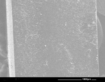
Fig. 1:Scanning electron microscopic (SEM) (×50) Micrograph of a fractured surface of a cross section of a sample of a specimen from the control group (Minacryl universal acrylic resin, no fibres)
Acrylic resin specimen containing silk fibres showed that the fibres could be seen protruding through the fracture surface (Fig. 2).
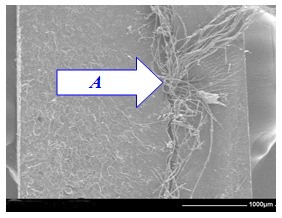
Fig. 2: SEM (×50) Micrograph of a fractured surface of a cross section of a sample of specimen from the silk group. The silk fibres (A) can be seen protruding from the fracture surface of the specimens
Acrylic resin specimen containing PMMA fibres revealed that the fibres are visible on the fracture surface (B) indicating integration within the resin (Fig. 3).
.
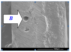
Fig. 3: SEM (×50) Micrograph of a fractured surface of a cross section of a sample of a specimen from the PMMA group. The PMMA fibre is visible on the fracture surface (B). The fibre is well integrated within the resin
Acrylic resin specimen containing polyethylene fibres is presented in Fig. 4, in which the polyethylene fibre can be seen protruding from the fracture surface (C).
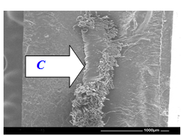
Fig. 4: SEM (×50) Micrograph of a fractured surface of a cross section of a sample specimen from the polyethylene group. The polyethylene fibre can be seen protruding from the fracture surface (C)
Fig. 5 showed the acrylic resin specimen containing glass strand fibres, the fractured surface appeared irregular and the glass fibres are visible (D).
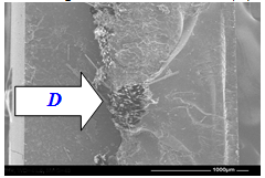
Fig. 5: SEM (×50) Micrograph of a fractured surface of a cross section of a sample of specimen from the glass strand group. The fracture surface is irregular and the glass fibres are visible (D)
The fractured surface of the acid etched acrylic resin specimen containing glass woven fibres showed that the woven glass fibres are well integrated within the PMMA acrylic resin matrix (E) as presented in Fig. 6.
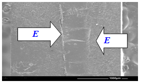
Fig. 6: SEM (×50) Micrograph of a fractured surface of a cross section of a sample of specimen from the glass woven group. The woven glass fibres are well integrated within the PMMA acrylic resin matrix (E)
The micrograph Fig. 7 of the acrylic resin specimen containing carbon fibres showed the carbon fibres at the fracture surface (F) and a crack at the fracture surface (G), which indicates that there is poor bonding between the carbon fibres and the PMMA acrylic resin matrix.
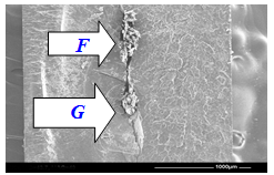
Fig. 7: SEM (×50) Micrograph of a fractured surface of a cross section of a sample of a specimen from the carbon fibres group. The micrograph shows the carbon fibres at the fracture surface (F) and a crack at the fracture surface (G), which indicates that there is poor bonding between the carbon fibres and the PMMA acrylic resin matrix
Transverse and impact strength tests revealed that the addition of glass fibres (strand) and polyethylene fibres produce a non-significant increase in the modulus of elasticity compared with control; the addition of glass fibres (woven and strand), polyethylene and carbon fibres to acrylic resin produced a non-significant increase in the modulus of rupture, the addition of carbon glass (strand and polyethylene fibres produced a significant increase in the impact strength.(2)
DiscussionThe denture base material can be reinforced in two ways: the entire denture base can be reinforced with a fibre weave, or localized fibre reinforcement can be accurately placed at the weak region of the denture. This reinforcement can be defined as total fibre reinforcement (TFR) and partial fibre reinforcement (PFR), respectively. If the fibre reinforcement is incorporated in the denture, PFR is the reinforcement of choice because it is easier to handle than TFR.(8)
The addition of carbon fibres has been reported to produce an improvement in the mechanical properties of acrylic resin but it has a potential toxicity and is black in colour.(2)
The addition of glass fibres(7) and polyethylene(9) has produced some exciting results. These have been successfully incorporated into acrylic resin and have been reported to produce significant improvement in term of strength.
Examination of a sample of specimens under the scanning electron microscope over a range of magnifications was performed. The ISO(10) 1567 and BSI(11) 2487 for denture base resin have specified transverse deformation limits of from 1 to2.5mm for a force of 15 to 35N. The mean breaking force of acrylic resin should not be less than 55N. In this respect the prepared samples with different fibres satisfies the standards after which they have been prepared for electron microscope scanning.
The interface between the fibres and the resin may play an important role in reinforcement. Examination of the specimens containing PMMA fibres showed that the fibres are well integrated within the matrix. The specimens demonstrated fracture through the fibres with no evidence that the fibres had been pulled out. However, the addition of the PMMA fibres compared with other studies weakened rather than strengthened the specimens even though they are seen to be well integrated within the matrix of the acrylic resin. The fibres may not prevent crack propagation and simply act as areas of stress concentration occupying spaces that should be occupied by the acrylic resin denture base material itself.
Examination of the specimens demonstrated the presence of a distinct interface between the fibres and the acrylic resin, particularly specimens containing silk, polyethylene and carbon fibres. It can be seen that the fibres are protruding from the fracture surface and there is evidence of crack propagation on the fractured surface of a specimen containing carbon fibres. Differences in the modulus of rupture and modulus of elasticity among the different fibres may be attributed to the degree of space these fibres occupy inside the specimens; the arrangement of fibres and the surface treatment of some fibres, for example the glass fibres which may improve the bond between the acrylic resin and the fibre.
ConclusionExamination of selected specimens under the scanning electron microscopy revealed that:
1. The specimen containing PMMA and glass woven fibres showed that the fibres are well integrated in the matrix of acrylic resin with no evidence of interface between the matrix and the fibres.
2. The specimen containing silk and carbon fibres showed that the fibres are protruding through the fracture surface which indicates that there is no bonding between the fibres and the PMMA acrylic resin matrix.
References1.
Jagger D, Harrison A, Jagger R, et al. The effect of the addition of PMMA fibres on some properties of high strength heat-cured acrylic resin denture base material. J Oral Rehabilitation 2003; 30: 231-235.
2.
Rahamneh A, Jagger D, Harrison A. The effect of the addition of different fibres on the transverse and impact strength of acrylic resin denture base material. Eur J Prosthodont Rest Dent 2003; 11: 75-81.
3.
Jagger DC, Harrison A, Jandt KD. The reinforcement of dentures. J Oral Rehabilitation 1999; 26: 185-194.
4.
Jagger D, Harrison A, Vowles R, et al. The effect of the addition of surface treated chopped and continuous PMMA fibres on some properties of acrylic resin. J Oral Rehabilitation 2001; 28: 865-872.
5.
Jagger DC, Harrison A, Jandt KD. An investigation of self-reinforced poly (methyl methacrylate) denture base acrylic resin using scanning electron and atomic force microscopy. Int J Prosthodon 2000; 13: 526-531.
6.
Jagger D, Harrison A. The effect of continuous PMMA fibres on some properties of acrylic resin denture base material. Eur J Prosthodont Rest Dent 2001; 8: 135-138.
7.
Vallittu PK. A review of fibre reinforced denture base resins. J Prosthodont 1996; 5: 270-276.
8.
Vallittu PK. Glass fibres reinforcement in repaired acrylic resin Removable dentures: Preliminary results of a clinical study. Quint Int 1997; 28: 39-44.
9.
Chow TW, Cheng YY, Ladizesky NH. Denture base reinforcement using woven polyethylene fibre. Int J Prosthodont. 1994; 7: 307-314.
10.
International Standard Organisation ISO. Specifications for denture base polymers. Geneva Switzerland. 1999; 1567.
11.
British Standard Specifications for denture base polymers. British Standards Institution, London, UK. BS 2000; 2487.